Z7 Coprocessor
A coprocessor for the Zybo Z7-10 board, providing functionality for floating point operations.
Architecture
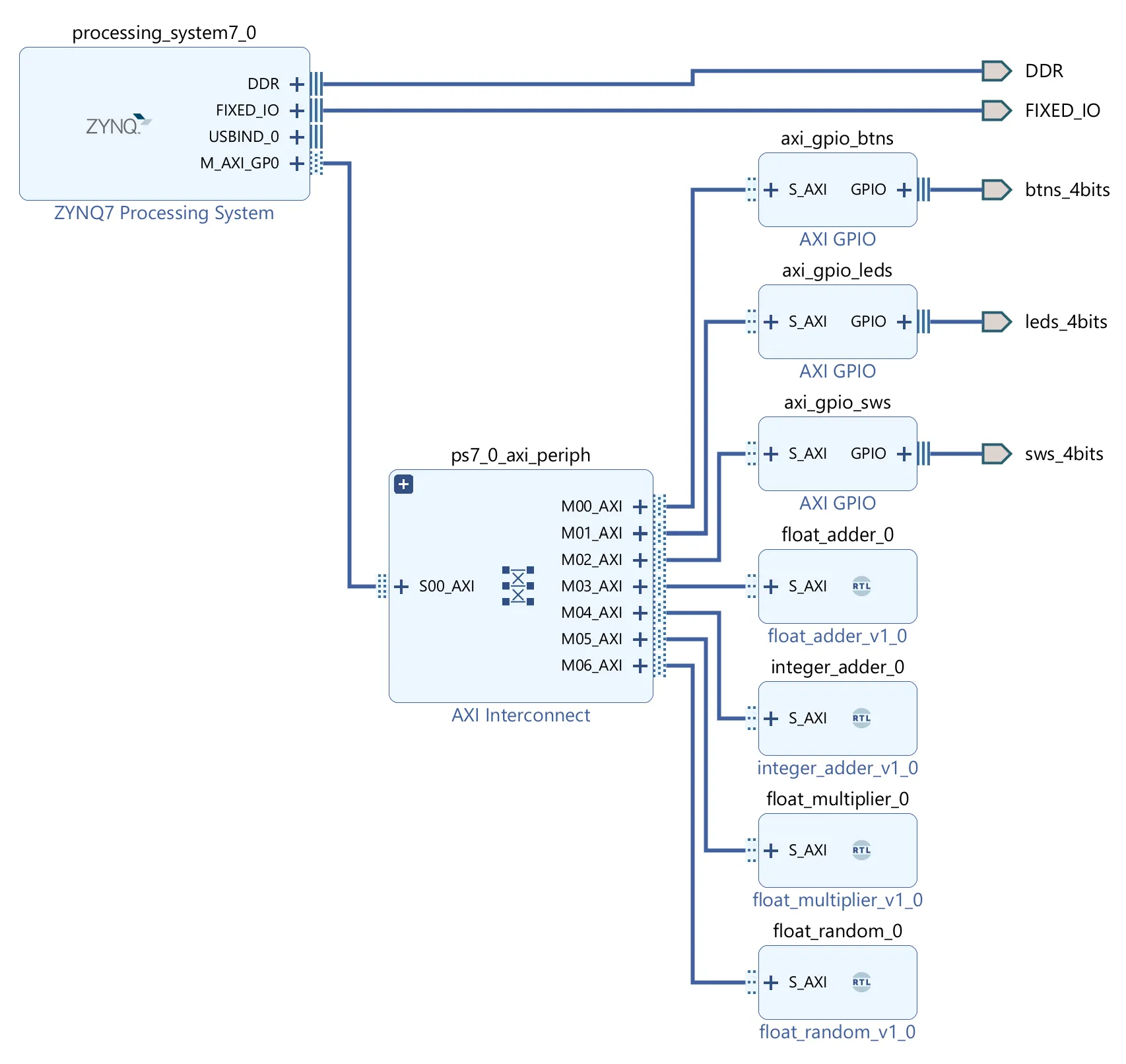
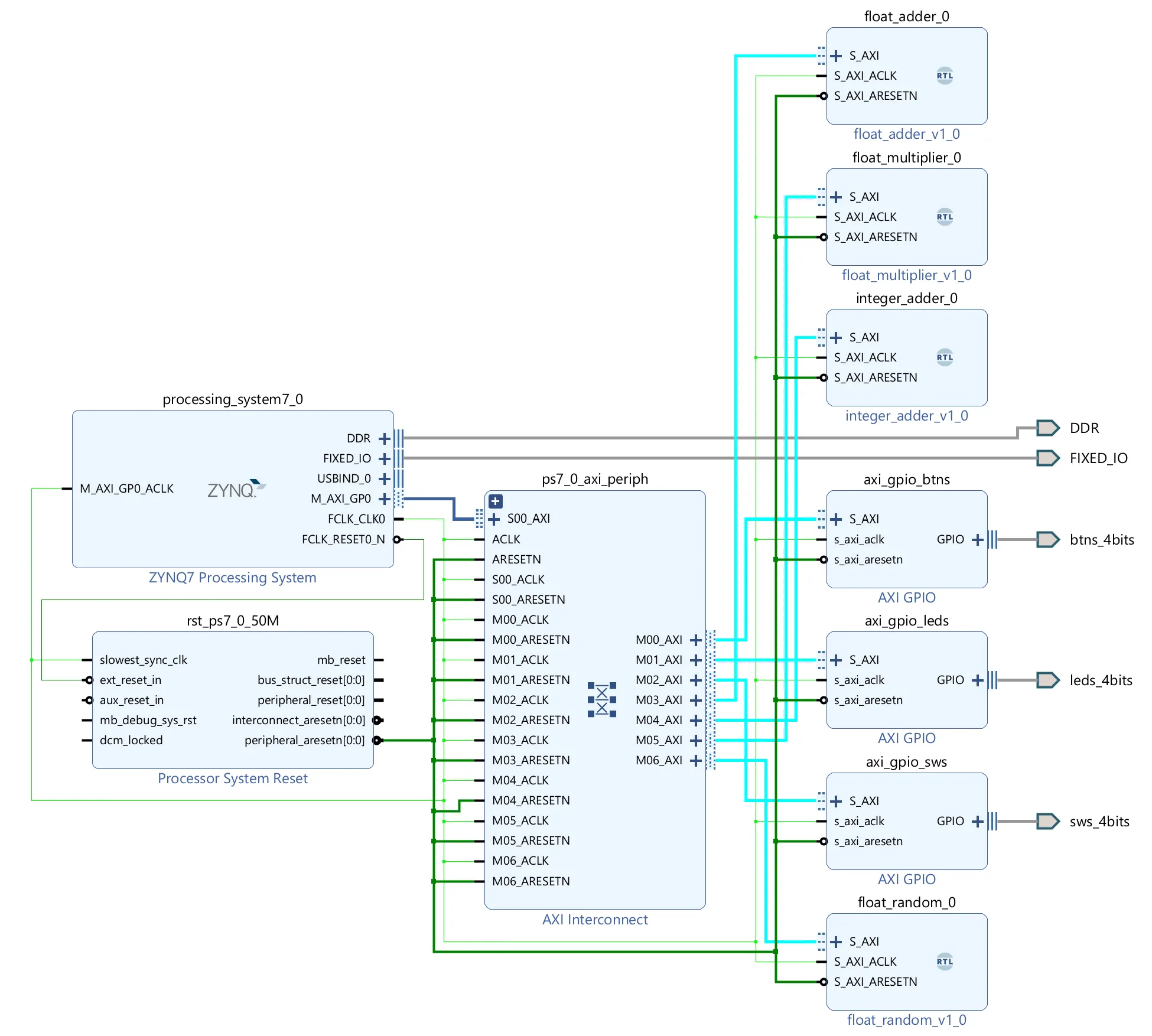
The Architecture is simple. The PS is connected to the PL via the AXI bus. All of the modules are a separate AXI MM slave, which is connected to the AXI bus. The PS can access the modules via the AXI bus, by using magic memory addresses (any address on the bus is equivalent to the same address in memory).

Floating Point Implementations
Compliant with the IEEE 754 standard, single precision (32-bit) floating point numbers.
Adder
This is my own design and implementation, this is not standard and not the most efficient.
-
Decide the exponent, as we want to maintain accuracy, we use the larger exponent and drop the least significant bits, not the most significant bits.
-
Shift the mantissa of the smaller number to the right, so that it is aligned with the larger number.
-
Add the mantissas together using signed arithmetic. NB: Add the implicit leading 1 to the mantissas and convert to signed as necessary.
-
Normalize the result, if the mantissa is larger than 1, shift it to the right and increment the exponent (the mantissa can only ever have a 1 bit overflow as we are adding two numbers). Look for the first 1 in the mantissa and shift it to the front, update the exponent accordingly. If you don’t find any ones, output 0. NB: All the previous steps used a larger data type, so we don’t have to worry about overflow.
Special cases:
- If either number is NaN, return NaN.
- If either number is infinity, return infinity.
Unary Minus
Just flip the sign bit.
Subtracter
Use the adder but flip the sign bit of the second number. This is equivalent to adding the first number and the negation of the second number.
Multiplier
This is my own design and implementation, this is not standard and not the most efficient.
- Add the exponents together, use unsigned arithmetic and subtract 127, due to the bias in the exponent representation.
- Multiply the mantissas together using long multiplication. NB: Add the implicit leading 1 to the mantissas.
- The resulting mantissa will either have one bit overflow, or already be normalised. If it has overflowed, shift the mantissa to the right and increment the exponent.
- The resulting sign is the XOR of the two signs.
Special cases:
- If either number is NaN, return NaN.
- If either number is infinity, return infinity.
- If either number is zero, return zero.
Divider
This is my own design and implementation, this is not standard and not the most efficient.
- Subtract the exponents, add back 127, due to the bias in the exponent representation.
- Divide the mantissas using long division over several clock cycles due to timing (this models quite nicely as you can just generate binary places per cycle in a pipeline). NB: Add the implicit leading 1 to the mantissas.
- Normalise the mantissa as above.
- The resulting sign is the XOR of the two signs.
Special cases:
- If either number is NaN, return NaN.
- If the dividend is infinity, return infinity.
- If the divisor is infinity, return zero.
- If the dividend is zero, return zero.
- If the divisor is zero, return NaN.
Random Number Generator
This is my own design and implementation, this is not standard and not the most efficient. However, I do not take credit for the concept, this has been a standard method of generating pseudo-random numbers in hardware for a long time.
A simple linear feedback shift register (LFSR) based random number generator.
Inspired by scrartch_vhdl.
Using a 28-bit LFSR with the polynomial (prime polynomial from University of Otago). So that is pretty random.
The LFSR is instantiated 23 times, each piped into the next, to give a set of 23 random bits each clock cycle.
Those 23 bits as the mantissa, an exponent of “01111111” (which is 127 in decimal, but 0 with the bias), and a sign bit of 0 (positive) for a number between 1 and 2.
Subtract 1 to get a number between 0 and 1.
The random number is quite uniform, but not perfectly random. The distribution is shown below.
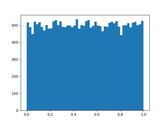
NB: This will never return 0, NaN, or infinity.
Square Root
Using Heron’s method (also known as the Babylonian method).
Building an FPGA Coprocessor
This document describes the process of building a simple FPGA coprocessor for floating point operations on the Zybo Z7-10 board. This coprocessor is not designed to provide high performance, but rather to illustrate the concepts involved in creating a custom coprocessor using SOC FPGA and floating point numbers.
Communication
How does the CPU communicate with the coprocessor?
The CPU (Processing System, PS) on the Z7-10 is an Arm Cortex-A9, capable of running Linux, but in this project it will run a standalone program.
The coprocessor (Programmable Logic, PL) is implemented in the FPGA fabric of the Z7-10 board.
The CPU conveniently has an AXI master interface, which can be used to communicate with the coprocessor. This can neatly integrate with how the floating point operations are divided into modules, each module being an AXI slave. All of the AXI interfaces will use AXI-MM (memory mapped), programs on the PS will use magic memory to interact with the PL.
An example interaction may look like this:
float a = 2.0f;
float b = 3.0f;

Xil_Out32(BASEADDR_A, to_bits(a));
Xil_Out32(BASEADDR_B, to_bits(b));

float o = to_float(Xil_In32(BASEADDR_O));
Where BASEADDR_X are the magic memory addresses for the coprocessor’s registers, and to_bits and to_float are functions that convert between floating point numbers and their bitwise representation as integers.
NB. Here it is necessary to take the bits of the float and gaslight the compiler into treating them as an integer, and vice versa. No conversion, purely nominal. This can be done using a union:
union int_float {
  u32 i;
  float f;
};
#define to_bits(x) ((union int_float){.f = x}.i)
#define to_float(x) ((union int_float){.i = x}.f)
The functions Xil_Out32 and Xil_In32 are provided by the Xilinx SDK, they are facades over unsafe memory access, a more sophisticated approach would provide an interface that abstracts away the low-level memory operations in a thread safe manner. Their implementations are as follows:
Click to expand
/*****************************************************************************/
/**
*
* @brief    Performs an input operation for a memory location by
*           reading from the specified address and returning the 32 bit Value
*           read  from that address.
*
* @param Addr contains the address to perform the input operation
*
* @return The 32 bit Value read from the specified input address.
*
******************************************************************************/
static INLINE u32 Xil_In32(UINTPTR Addr)
{
  return *(volatile u32 *) Addr;
}

/*****************************************************************************/
/**
*
* @brief    Performs an output operation for a memory location by writing the
*           32 bit Value to the the specified address.
*
* @param Addr contains the address to perform the output operation
* @param Value contains the 32 bit Value to be written at the specified
*           address.
*
* @return None.
*
******************************************************************************/
static INLINE void Xil_Out32(UINTPTR Addr, u32 Value)
{
  /* write 32 bit value to specified address */
#ifndef ENABLE_SAFETY
  volatile u32 *LocalAddr = (volatile u32 *)Addr;
  *LocalAddr = Value;
#else
  XStl_RegUpdate(Addr, Value);
#endif
}
Here is an example topology of the AXI interconnectivity:

Vitis
Vitis is the software development environment provided by Xilinx for developing applications for their FPGA-based systems. It integrates with Vivado, the hardware design tool, allowing for seamless development of both hardware and software components.
A new Vivado/Vitis project can be created using the step by step process documented in this guide.
The benefit of using Vitis is that it will synchronise the hardware and software projects, generating the necessary drivers and headers for the custom hardware modules created in Vivado. This means that I can reference a constant like XPAR_AXI_GPIO_BTNS_BASEADDR in my C code, and it will correspond to the correct memory address for the GPIO module created in Vivado. Then the build button in Vitis will compile an image for the PS that includes my program and a copy of the .bit file to program the PL on boot and program the PS over JTAG.
The disbenefit of using Vitis is that it is quite frustrating to use, so you must ensure that all the setup guide is followed perfectly or you may run into problems such as out of date .bit files being used, which will lead to unexpected behaviour when running the program on the board (and headaches).
Floating Point Representation
The most common floating point representation is defined by the IEEE 754 standard. I will use single precision (32-bit) floating point numbers based on that standard so that I can use the standard C library functions to test my implementations and easily convert.
In this representation, a floating point number is divided into three parts:
- Sign bit (s): 1 bit that indicates the sign of the number (0 for positive, 1 for negative).
- Exponent (e): 8 bits that represent the exponent (not a signed integer, but a biased representation with a bias of 127).
- Mantissa (m): 23 bits that represent the fractional part of the number, with an implicit leading 1.
Implementing my functions
Adder
The simplest way I can see to add two floating point numbers is to convert them to fixed point numbers with the same exponent, add them together, then normalise back to floating point.
-
Always use the larger exponent for the fixed point representation to ensure that the most significant bits are preserved.
-
Shift the mantissa of the smaller number to the right, so that it is aligned with the larger number.
-
Add the mantissas together using signed arithmetic. NB: Add the implicit leading 1 to the mantissas and convert to signed as necessary.
-
Normalize the result, if the mantissa is larger than 1, shift it to the right and increment the exponent (the mantissa can only ever have a 1 bit overflow as we are adding two numbers). Look for the first 1 in the mantissa and shift it to the front, update the exponent accordingly. If you don’t find any ones, output 0. NB: All the previous steps used a larger data type, so we don’t have to worry about overflow.
Special cases:
- If either number is NaN, return NaN.
- If either number is infinity, return infinity.
Digital Logic
Decode inputs amd define variables:
function safe_add(a, b : my_float) return my_float is
  variable a_sign        : STD_LOGIC                     := a(31);
  variable a_exp         : STD_LOGIC_VECTOR(7 downto 0)  := a(30 downto 23);
  variable a_man         : STD_LOGIC_VECTOR(22 downto 0) := a(22 downto 0);
  variable b_sign        : STD_LOGIC                     := b(31);
  variable b_exp         : STD_LOGIC_VECTOR(7 downto 0)  := b(30 downto 23);
  variable b_man         : STD_LOGIC_VECTOR(22 downto 0) := b(22 downto 0);
  variable exp_diff      : UNSIGNED(7 downto 0)          := UNSIGNED(a_exp) - UNSIGNED(b_exp);

  -- Will store the mantissas with implicit leading 1 bit added
  variable a_man_1       : UNSIGNED(23 downto 0);
  variable b_man_1       : UNSIGNED(23 downto 0);

  -- Will hold the signed result of the addition/subtraction
  variable signed_man    : SIGNED(25 downto 0);

  -- Will hold the unsigned result of the addition/subtraction before
  -- normalisation (with an extra leading bit for overflow)
  variable overflow_man  : STD_LOGIC_VECTOR(24 downto 0);

  -- Will hold the result sign bit
  variable sign          : STD_LOGIC;
begin
Handle denormalised numbers:
  -- If the exponent has minimum value (all zero), special rules for
  -- denormalized values are followed.
  -- The exponent value is set to 2-126 and the "invisible" leading bit
  -- for the mantissa is no longer used.
  if a_exp = fill('0', 8) then
    a_man_1 := UNSIGNED('0' & a_man);
    a_exp   := "00000001"; -- Set exponent to 2-126
  else
    a_man_1 := UNSIGNED('1' & a_man);
  end if;
  if b_exp = fill('0', 8) then
    b_man_1 := UNSIGNED('0' & b_man);
    b_exp   := "00000001"; -- Set exponent to 2-126
  else
    b_man_1 := UNSIGNED('1' & b_man);
  end if;
Perform addition/subtraction based on sign bits:
  if a_sign = b_sign then
    -- Simple addition case and maintain the sign
    sign := a_sign;
    if exp_diff = 0 then
      overflow_man := STD_LOGIC_VECTOR(('0' & b_man_1) + ('0' & a_man_1));
    else
      -- Shift the mantissa so that both a and b have the same exponent
      overflow_man := STD_LOGIC_VECTOR(('0' & shift_right(b_man_1, TO_INTEGER(exp_diff))) + ('0' & a_man_1));
    end if;
  elsif a_sign = '1' then
    if exp_diff = 0 then
      signed_man := SIGNED("00" & b_man_1) - SIGNED("00" & a_man_1);
      -- Convert twos compliment into sign and magnitude
      if signed_man(25) = '1' then
        sign         := '1';
        overflow_man := STD_LOGIC_VECTOR(not(UNSIGNED(signed_man(24 downto 0))) + 1);
      else
        sign         := '0';
        overflow_man := STD_LOGIC_VECTOR(signed_man(24 downto 0));
      end if;
    else
      -- Shift the mantissa so that both a and b have the same exponent
      signed_man := SIGNED("00" & shift_right(b_man_1, TO_INTEGER(exp_diff))) - SIGNED("00" & a_man_1);
      -- Convert twos compliment into sign and magnitude
      if signed_man(25) = '1' then
        sign         := '1';
        overflow_man := STD_LOGIC_VECTOR(not(UNSIGNED(signed_man(24 downto 0))) + 1);
      else
        sign         := '0';
        overflow_man := STD_LOGIC_VECTOR(signed_man(24 downto 0));
      end if;
    end if;
  else -- b_sign = '1'
    if exp_diff = 0 then
      signed_man := SIGNED("00" & a_man_1) - SIGNED("00" & b_man_1);
      -- Convert twos compliment into sign and magnitude
      if signed_man(25) = '1' then
        sign         := '1';
        overflow_man := STD_LOGIC_VECTOR(not(UNSIGNED(signed_man(24 downto 0))) + 1);
      else
        sign         := '0';
        overflow_man := STD_LOGIC_VECTOR(signed_man(24 downto 0));
      end if;
    else
      -- Convert twos compliment into sign and magnitude
      signed_man := SIGNED("00" & a_man_1) - SIGNED("00" & shift_right(b_man_1, TO_INTEGER(exp_diff)));
      -- Convert twos compliment into sign and magnitude
      if signed_man(25) = '1' then
        sign         := '1';
        overflow_man := STD_LOGIC_VECTOR(not(UNSIGNED(signed_man(24 downto 0))) + 1);
      else
        sign         := '0';
        overflow_man := STD_LOGIC_VECTOR(signed_man(24 downto 0));
      end if;
    end if;
  end if;
This may look like a lot of logic will be created, but in reality there is a lot of duplicated logic that can be optimised away by the synthesizer. Usually the shift_right function would be but in all three cases where it is used here, the logic is reused and most of it minimises away.
I am writing code in an imperative way that makes logical sense to humans, the synthesiser will take care of optimising it down to the minimum logic required. This technique is a good thing, but only if you understand what the resulting logic will look like.
Normalize result and pack into output format:
  if overflow_man(24) = '1' then
    -- If the output requires a higher exponent to be normalised
    -- The only possible case is a single bit overflow
    return sign & STD_LOGIC_VECTOR(UNSIGNED(a_exp) + 1) & overflow_man(23 downto 1);
  elsif overflow_man(23) = '0' then
    -- If the output requires a lower exponent to be normalised
    for I in 22 downto 0 loop
      if overflow_man(I) = '1' then
        return sign
        & STD_LOGIC_VECTOR(UNSIGNED(a_exp) - (23 - I))
        & overflow_man((I - 1) downto 0) & fill('0', 23 - I);
      end if;
    end loop;
    -- If overflow mantissa does not contain a '1', output 0
    return ZERO;
  else
    -- Simple case where the output is already normalised
    return my_float(sign & a_exp & overflow_man(22 downto 0));
    -- for some reason xsim does not like the return type, thus the cast
  end if;
end function safe_add;
Similarly to above: for loops aren’t usually a good idea, but here I am simply describing to the synthesiser what I want the output to be and it will create the necessary logic to achieve that. In this case, it boils down to a deep chain of LUTs (not great, but not terrible). It is important to remember that I am not describing an iterative process, though the code would work as one.
Top level addition function:
function "+" (a, b : my_float) return my_float is
  variable a_exp     : STD_LOGIC_VECTOR(7 downto 0) := a(30 downto 23);
  variable b_exp     : STD_LOGIC_VECTOR(7 downto 0) := b(30 downto 23);
begin

  -- Handle +-infinity and +-NaN
  if a_exp = fill('1', 8) then
    return a;
  end if;
  if b_exp = fill('1', 8) then
    return b;
  end if;

  -- Always use the biggest exponent to prevent losing the most significant data.
  if UNSIGNED(a_exp) < UNSIGNED(b_exp) then
    return safe_add(b, a);
  end if;

  return safe_add(a, b);
end function "+";
This is a wrapper function that handles infinite and NaN inputs, and ensures that the larger exponent is always used as the base for the addition.
Connecting to the AXI interface
The adder module will have an AXI slave interface, with registers for the two input operands and one output result. The output will not be valid until one clock cycle after both inputs have been written. Otherwise, it is a standard AXI MM slave interface based on Xilinx’s AXI IP templates.
This AXI MM interface can then be connected in the Vivado block design to the AXI interconnect, allowing the PS to communicate with it.
Using it with the CPU
Once the design is exported into Vitis, the generated header files will contain the necessary definitions to access the adder module’s registers. The CPU program can then write the input operands to the appropriate registers and read back the result.
#include "sleep.h"
#include "xil_io.h"
#include "xil_printf.h"
#include "xil_types.h"
#include "xparameters.h"

// Get devices from xparameters.h
#define OPPERATION_A 0
#define OPPERATION_B 4
#define OPPERATION_O 8

#define FLOAT_ADDER_BASEADDR XPAR_FLOAT_ADDER_0_BASEADDR
#define FLOAT_ADDER_BASEADDR_A FLOAT_ADDER_BASEADDR + OPPERATION_A
#define FLOAT_ADDER_BASEADDR_B FLOAT_ADDER_BASEADDR + OPPERATION_B
#define FLOAT_ADDER_BASEADDR_O FLOAT_ADDER_BASEADDR + OPPERATION_O

union int_float {
  u32 i;
  float f;
};
#define to_bits(x) ((union int_float){.f = x}.i)
#define to_float(x) ((union int_float){.i = x}.f)

int main() {
  float a = 2.0f;
  float b = 3.0f;

  xil_printf("##########################################################\r\n");
  xil_printf("#\r\n");
  xil_printf("# ADDER: \r\n");
  xil_printf("#\r\n");
  xil_printf("##########################################################\r\n");
  xil_printf("\r\n");

  xil_printf("On ARM:\r\n");
  xil_printf("A: %x\t", to_bits(a));
  xil_printf("B: %x\t", to_bits(b));
  xil_printf("O: %x\t", to_bits(a + b));
  xil_printf("\r\n");

  // Write inputs to FPGA
  Xil_Out32(FLOAT_ADDER_BASEADDR_A, to_bits(a));
  Xil_Out32(FLOAT_ADDER_BASEADDR_B, to_bits(b));

  // Validate the inputs were written correctly, read output and
  // compare with standard library result
  xil_printf("On FPGA:\r\n");
  xil_printf("A: %x\t", Xil_In32(FLOAT_ADDER_BASEADDR_A));
  xil_printf("B: %x\t", Xil_In32(FLOAT_ADDER_BASEADDR_B));
  xil_printf("O: %x\t", Xil_In32(FLOAT_ADDER_BASEADDR_O));
  xil_printf("O: %x\t", to_bits(
    to_float(Xil_In32(FLOAT_ADDER_BASEADDR_A))
    + to_float(Xil_In32(FLOAT_ADDER_BASEADDR_B))
  ));
  xil_printf("\r\n");

  return 0;
}
NB: Unfortunately, there is no built in way to print floating point numbers using xil_printf, so I am printing the bitwise representation as hexadecimal instead.
Unary Minus
Just flip the sign bit!
function "-" (a : my_float) return my_float is
begin
  return not(a(31)) & a(30 downto 0);
end function "-";
Subtractor
Add the first number to the negation of the second number.
function "-" (a, b : my_float) return my_float is
begin
  return a + (-b);
end function "-";
Multiplier
The multiplication of two floating point numbers can be broken down into multiplying the mantissas and adding the exponents.
- Add the exponents together, use unsigned arithmetic and subtract 127, due to the bias in the exponent representation.
- Multiply the mantissas together using long multiplication. NB: Add the implicit leading 1 to the mantissas.
- The resulting mantissa will either have one bit overflow, or already be normalised. If it has overflowed, shift the mantissa to the right and increment the exponent.
- The resulting sign is the XOR of the two signs.
Special cases:
- If either number is NaN, return NaN.
- If either number is infinity, return infinity.
- If either number is zero, return zero.
Digital Logic
Decode inputs and define variables:
function "*" (a, b : my_float) return my_float is
  variable a_sign    : STD_LOGIC                     := a(31);
  variable a_exp     : STD_LOGIC_VECTOR(7 downto 0)  := a(30 downto 23);
  variable a_man     : STD_LOGIC_VECTOR(22 downto 0) := a(22 downto 0);
  variable b_sign    : STD_LOGIC                     := b(31);
  variable b_exp     : STD_LOGIC_VECTOR(7 downto 0)  := b(30 downto 23);
  variable b_man     : STD_LOGIC_VECTOR(22 downto 0) := b(22 downto 0);

  -- 1 bit for overflow (1 <= x,y < 10 so 1 <= x * y < 100), leading 1 is implicit, 24 bits for the mantissa
  variable man_sum   : UNSIGNED(24 downto 0)         := UNSIGNED("01" & a_man);

  variable sign      : STD_LOGIC                     := a_sign xor b_sign;
  variable man       : STD_LOGIC_VECTOR(22 downto 0);
  variable exp       : UNSIGNED(7 downto 0) := UNSIGNED(a_exp) + UNSIGNED(b_exp) - "01111111"; -- Subtract the bias of 127
begin
Handle special cases:
  -- TODO: denormalized numbers (not urgent, none of these implementations output denormalised
  -- numbers yet)

  -- Handle zero
  if a(30 downto 0) = fill('0', 31) or a(30 downto 0) = fill('0', 31) then
    return fill('0', 32);
  end if;

  -- Handle +-infinity and +-NaN
  if a_exp = fill('1', 8) then
    return sign & a(30 downto 0);
  end if;
  if b_exp = fill('1', 8) then
    return my_float(sign & b(30 downto 0)); -- for some reason xsim does not like the return type, thus the cast
  end if;
Perform multiplication of mantissas:
  -- a1 * b1 is the sum of a1 bit shifted to all of the bits in b1 that are 1

  -- Long multiplication of the mantissa
  -- We start with the leading 1 in the variable already.
  G1 : for I in 0 to 22 loop
    if b_man(22 - I) = '1' then
      man_sum := man_sum + UNSIGNED(fill('0', I + 1) & '1' & a_man(22 downto I + 1));
    else
      man_sum := man_sum;
    end if;
  end loop;
Usually a for loop with nested additions would be bad, but here I know that the synthesiser will minimise the logic into a nearly flat set of LUTs and a carry chain.
Normalize result and pack into output format:
  -- Handle overflow
  if man_sum(24) = '1' then
    -- If the mantissa overflows, shift it right and increment the exponent
    -- we check for the leading 1, so we can safely take the 23 bits and omit the leading 1
    man := STD_LOGIC_VECTOR(man_sum(23 downto 1));
    exp := exp + 1;
  else
    -- If the mantissa does not overflow, just take the lower
    -- there will always be a leading 1, so we can safely take the lower 23 bits
    -- 1.xxxx * 1.zzzz = 1.yyyy
    man := STD_LOGIC_VECTOR(man_sum(22 downto 0));
  end if;

  return my_float(sign & STD_LOGIC_VECTOR(exp) & man);
  -- for some reason xsim does not like the return type, thus the cast

end function "*";
That was easy? It was easier and more efficient than the adder.
Divider
The division of two floating point numbers can be broken down into dividing the mantissas and subtracting the exponents.
- Subtract the exponents, add back 127, due to the bias in the exponent representation.
- Divide the mantissas using long division over several clock cycles due to timing (this pipelines quite nicely as you can just generate binary places per cycle in a pipeline). NB: Add the implicit leading 1 to the mantissas.
- Normalise the mantissa as above.
- The resulting sign is the XOR of the two signs.
Special cases:
- If either number is NaN, return NaN.
- If the dividend is infinity, return infinity.
- If the divisor is infinity, return zero.
- If the dividend is zero, return zero.
- If the divisor is zero, return NaN.
NB: This is no longer a pure function due to the pipelining, so it will be implemented as an entity with a clock and reset input. A pure function version is implemented in float_pkg.vhd for completeness.
Digital Logic
Interface:
entity pipeline_divider is
  generic (
    pipeline_depth : INTEGER := 4 -- Number of pipeline stages
  );
  port (
    clk  : in  STD_LOGIC;
    rst  : in  STD_LOGIC;
    a, b : in  my_float;
    q    : out my_float
  );
end entity;
Stages:
architecture rtl of pipeline_divider is

  type stage_rec is record
    skip  : STD_LOGIC; -- used to skip stages for zero, infinity, NaN
    sign  : STD_LOGIC;
    exp   : UNSIGNED(7 downto 0);
    rema  : UNSIGNED(24 downto 0);
    divi  : UNSIGNED(24 downto 0);
    mfull : STD_LOGIC_VECTOR(23 downto 0);
  end record;

  type stage_array is array (0 to pipeline_depth - 1) of stage_rec;
  signal pipeline          : stage_array;
Initial Stage - Decode inputs and handle special cases:
  function init_stage(a, b : my_float) return stage_rec is
    variable r               : stage_rec;

    variable a_sign          : STD_LOGIC                     := a(31);
    variable a_exp           : STD_LOGIC_VECTOR(7 downto 0)  := a(30 downto 23);
    variable a_man           : STD_LOGIC_VECTOR(22 downto 0) := a(22 downto 0);
    variable b_sign          : STD_LOGIC                     := b(31);
    variable b_exp           : STD_LOGIC_VECTOR(7 downto 0)  := b(30 downto 23);
    variable b_man           : STD_LOGIC_VECTOR(22 downto 0) := b(22 downto 0);
  begin
    -- Division by zero, return NaN
    if b(30 downto 0) = fill('0', 31) then
      r.skip  := '1';
      r.sign  := a_sign xor b_sign;
      r.exp   := UNSIGNED(fill('1', 8)); -- NaN
      r.mfull := fill('0', 24);
    end if;
    -- Handle zero (0 / x = 0)
    if a(30 downto 0) = fill('0', 31) then
      r.skip  := '1';
      r.sign  := a_sign xor b_sign;
      r.exp   := (others => '0');
      r.mfull := fill('0', 24);
      return r;
    end if;

    -- Handle +-infinity and +-NaN
    if a_exp = fill('1', 8) then
      r.skip  := '1';
      r.sign  := a_sign xor b_sign;
      r.exp   := UNSIGNED(fill('1', 8));
      r.mfull := '1' & a_man;
      return r;
    end if;
    if b_exp = fill('1', 8) then
      if b_man /= fill('0', 23) then
        -- Division by NaN, return NaN
        r.skip  := '1';
        r.sign  := a_sign xor b_sign;
        r.exp   := UNSIGNED(fill('1', 8)); -- NaN
        r.mfull := '1' & b_man;
        return r;
      else
        -- Division by infinity, return zero (my opinion)
        r.skip  := '1';
        r.sign  := a_sign xor b_sign;
        r.exp   := UNSIGNED(fill('0', 8));
        r.mfull := fill('0', 24);
        return r;
      end if;
    end if;

    -- Normal case: initialize stage record
    r.skip  := '0';
    r.sign  := a_sign xor b_sign;
    r.exp   := UNSIGNED(a_exp) - UNSIGNED(b_exp) + "01111111";
    r.rema  := UNSIGNED('1' & a_man & '0');
    r.divi  := UNSIGNED('1' & b_man & '0');
    r.mfull := (others => '0');
    return r;
  end function;
Pipeline stage function - Perform long division on specified range:
  function do(s : stage_rec; hi, lo : INTEGER)
    return stage_rec is
    variable t : stage_rec := s;
  begin
    if t.skip = '1' then
      return t; -- skip processing if already marked to skip
    end if;
    -- do specified bits of long division
    for i in hi downto lo loop
      if t.rema >= t.divi then
        t.mfull(i) := '1';
        t.rema     := t.rema - t.divi;
      end if;
      t.divi := '0' & t.divi(24 downto 1);
    end loop;
    return t;
  end function;
Pack function - Normalize and pack output:
  function pack(s : stage_rec) return my_float is
  begin
    if s.skip = '1' then
      return my_float(s.sign & STD_LOGIC_VECTOR(s.exp) & s.mfull(22 downto 0));
      -- for some reason xsim does not like the return type, thus the cast
    end if;

    if s.mfull(23) = '1' then
      -- Simple case where the output is already normalised
      return my_float(s.sign & STD_LOGIC_VECTOR(s.exp) & s.mfull(22 downto 0)); -- for some reason xsim does not like the return type, thus the cast
    else
      -- If the output requires a lower exponent to be normalised
      for I in 22 downto 0 loop
        if s.mfull(I) = '1' then
          return s.sign
          & STD_LOGIC_VECTOR(s.exp - (23 - I))
          & s.mfull((I - 1) downto 0) & fill('0', 23 - I);
        end if;
      end loop;
      -- If overflow mantissa does not contain a '1', output 0
      return (others => '0');
    end if;
  end function;
Main process - Pipeline registers and control:
begin

  -- pipeline registers
  process (clk) is
    variable p0 : stage_rec;
  begin
    if rst = '1' then
      for i in 0 to pipeline_depth - 1 loop
        pipeline(0) <= (
          skip  => '0',
          sign  => '0',
          exp   => (others => '0'),
          rema  => (others => '0'),
          divi  => (others => '0'),
          mfull => (others => '0')
        );
      end loop;
      q <= (others => '0');
    elsif rising_edge(clk) then
      p0 := init_stage(a, b);
      pipeline(0) <=
                    do(
                      p0,
                      24 / pipeline_depth * (pipeline_depth) - 1,
                      24 / pipeline_depth * (pipeline_depth - 1)
                    );
      for i in 1 to pipeline_depth - 1 loop
        pipeline(i) <=
                      do(
                        pipeline(i - 1),
                        24 / pipeline_depth * (pipeline_depth - i) - 1,
                        24 / pipeline_depth * (pipeline_depth - i - 1)
                      );
      end loop;
      q <= pack(pipeline(pipeline_depth - 1));
    end if;
  end process;

end architecture;
Connecting to the AXI interface
The only difference here is that valid of the output will be kept low until pipeline_depth + 1 clock cycles after both inputs have been written. In an ideal world, the pipeline would early exit for finite divisions and special cases (NaN, infinity, zero) and thus the output would be valid earlier.
Comparator
Due to normalisation, if a number has a higher exponent it must be larger (assuming both numbers are positive). Thus the comparison can be done by first comparing the exponents, then the mantissas if the exponents are equal. The sign bits must also be taken into account.
- If the sign bits are different, the positive number is larger.
- If both numbers are negative, output the opposite of the comparison result.
- If both numbers are positive, compare the exponents:
- If one exponent is larger, that number is larger.
- If the exponents are equal, compare the mantissas:
- If one mantissa is larger, that number is larger.
- If the mantissas are equal, the numbers are equal.
Random
Goal: Generate (pseudo-)random floating point numbers between 0 and 1.
As the output should be between 0 and 1, the exponent will always be 01111111 (biased representation of 0), and the sign bit will always be 0. Thus only the mantissa needs to be randomised. NB: this will produce numbers in the range , so to get numbers in the range I will need to subtract 1.0 from the output.
Given that true random is not a possibility here, a pseudo-random number generator (PRNG) will be used. A simple linear feedback shift register (LFSR) can be implemented in hardware to generate pseudo-random bits.
Inspired by scrartch_vhdl.
To generate good quality random numbers, a big optimal LFSR is required. The easiest way to find big prime polynomials is to google them (Thanks University of Otago).
I am going to use a 28-bit LFSR with the polynomial:
I will take the bottom bit of 23 iterations of the LFSR to form the mantissa of the floating point number (nice and random).
I think it would take at least consecutive numbers to be able to predict the next number and since I can generate a new number every clock cycle. it would be difficult to keep in sync with the sequence unless you read numbers very quickly. I think that is sufficient.
NB: This is not a cryptographically secure PRNG, but it is sufficient for simulations and non-security related tasks. It also will never generate NaN, infinity or 1.0.
Digital Logic
Interface:
entity random is
  generic (
    seed : STD_LOGIC_VECTOR(27 downto 0) := "0000000000000000000000000001"
  );
  port (
    clk : in  STD_LOGIC;
    rst : in  STD_LOGIC;
    rnd : out my_float
  );
end entity;
LFSR:
architecture rtl of random is

  constant lfsr_init : STD_LOGIC_VECTOR(27 downto 0) := seed;
  signal lfsr        : STD_LOGIC_VECTOR(27 downto 0) := lfsr_init;

  signal rnd_man     : STD_LOGIC_VECTOR(22 downto 0);

begin

  process (clk)
    variable lfsr_i : STD_LOGIC_VECTOR(27 downto 0);
  begin
    if rising_edge(clk) then
      if rst = '1' then
        lfsr <= lfsr_init;
      else
        lfsr_i := lfsr;
        G1 : for i in 0 to 22 loop
          --                               27 and 24 here correspond to the taps in the LFSR
          --                               from the powers 28 and 25.
          lfsr_i := lfsr_i(26 downto 0) & (lfsr_i(27) xor lfsr_i(24));
          rnd_man(i) <= lfsr_i(0);
        end loop G1;
        lfsr <= lfsr_i;
      end if;
    end if;
  end process;
Pack output and adjust range:
  -- Convert the LFSR output to a floating-point number
  -- Subtracting 1 to ensure the result is in the range [0, 1),
  -- this should get minimized away to very little extra logic.
  --                       sign +  exponent  + mantissa
  rnd <= (my_float("0" & "01111111" & rnd_man) - ONE);

end architecture;
Square Root
The square root can be calculated using Heron’s method (also known as the Babylonian method), which is an iterative algorithm that converges to the square root of a number. The formula for Heron’s method is:
Digital Logic
entity sqrt is
  port (
    clk   : in  STD_LOGIC;
    rst   : in  STD_LOGIC;
    new_a : in  STD_LOGIC; -- Signal to indicate new input
    a     : in  my_float;
    q     : out my_float;
    valid : out STD_LOGIC
  );
end entity;

architecture rtl of sqrt is

  signal x_n              : my_float             := ONE;

  signal frac             : my_float             := (others => '0');
  signal frac_invalid_cnt : UNSIGNED(2 downto 0) := "000";

  signal root_invalid_cnt : UNSIGNED(3 downto 0) := "0000";

  signal q_valid          : STD_LOGIC            := '0';

begin

  valid <= q_valid;

  -- could utilise more cycles here
  divider_inst : entity work.pipeline_divider
    generic map(
      pipeline_depth => 6
    )
    port map(
      clk => clk,
      rst => rst,
      a   => a,
      b   => x_n,
      q   => frac
    );

  process (clk, rst)
    variable x_n1 : my_float;
  begin
    if rising_edge(clk) then
      if rst = '1' or new_a = '1' then
        x_n              <= ONE;
        frac_invalid_cnt <= to_unsigned(7, 3);
        root_invalid_cnt <= to_unsigned(15, 4);
        q       <= (others => '0');
        q_valid <= '0';
      else
        if STD_LOGIC_VECTOR(frac_invalid_cnt) = "000" then
          frac_invalid_cnt <= to_unsigned(7, 3);
          -- this should minimize away the mantissa part of the
          -- multiplier and just decrement the exponent
          x_n1 := HALF * (x_n + frac);

          -- The value will be valid after 15 iterations, but will continue
          -- to improve until a new input is given.
          if STD_LOGIC_VECTOR(root_invalid_cnt) = "0000" or x_n1 = x_n then
            q       <= x_n1;
            q_valid <= '1';
          else
            root_invalid_cnt <= root_invalid_cnt - 1;
          end if;
        else
          frac_invalid_cnt <= frac_invalid_cnt - 1;
          x_n1 := x_n;
        end if;
        x_n <= x_n1;

        if a(31) = '1' then -- Negative input
          q       <= NaN;
          q_valid <= '1';
        end if;
      end if;
    end if;
  end process;

end architecture rtl;
Testing
Discrete Tests
Throughout the development, I tested random cases and expected edge cases on both the simulator and the FPGA hardware. The simulator allowed for quick iteration and debugging, while the FPGA testing ensured that the design worked correctly in real hardware.
All of the testing code is found in /vitis/app_component/src/main.c
Big Calculation
Calculating π
To further test my implementations, I created a program that calculates the value of π using the Leibniz infinite series:
float pi = 0.0f;
int sign = 0;
for (int i = 0; i < 1000000; i++) {
  Xil_Out32(FLOAT_DIVIDER_BASEADDR_A, to_bits(2.0f * i + 1.0f));
  if (sign == 1) {
    sign = 0;
    Xil_Out32(FLOAT_ADDER_BASEADDR_A, to_bits(pi));
    Xil_Out32(FLOAT_ADDER_BASEADDR_B, Xil_In32(FLOAT_DIVIDER_BASEADDR_O));
    pi = to_float(Xil_In32(FLOAT_ADDER_BASEADDR_O));
  } else {
    sign = 1;
    Xil_Out32(FLOAT_ADDER_BASEADDR_A, to_bits(pi));
    Xil_Out32(FLOAT_ADDER_BASEADDR_B, -Xil_In32(FLOAT_DIVIDER_BASEADDR_O));
    pi = to_float(Xil_In32(FLOAT_ADDER_BASEADDR_O));
  }
}
Xil_Out32(FLOAT_MULTIPLIER_BASEADDR_A, to_bits(pi));
Xil_Out32(FLOAT_MULTIPLIER_BASEADDR_B, to_bits(4.0f));
pi = to_float(Xil_In32(FLOAT_MULTIPLIER_BASEADDR_O));
xil_printf("Calculated PI (Leibniz): %x\r\n", to_bits(pi));
I also used an approximation of π using the area of a circle inscribed in a square. By generating random points within the square and checking how many fall within the circle, I can estimate π using the ratio of points inside the circle to the total number of points.
int inside_circle = 0;
int total_points = 1000000;  // Number of random points to generate
for (int i = 0; i < total_points; i++) {
  // Generate random x and y coordinates in the range [-1, 1]
  // x = 2 * rnd - 1;
  Xil_Out32(FLOAT_MULTIPLIER_BASEADDR_A, Xil_In32(FLOAT_RANDOM_BASEADDR_O));
  Xil_Out32(FLOAT_MULTIPLIER_BASEADDR_B, to_bits(2.0f));
  Xil_Out32(FLOAT_ADDER_BASEADDR_A, to_bits(-1.0f));
  Xil_Out32(FLOAT_ADDER_BASEADDR_B, Xil_In32(FLOAT_MULTIPLIER_BASEADDR_O));
  float x = Xil_In32(FLOAT_ADDER_BASEADDR_O);
  // y = 2 * rnd - 1;
  Xil_Out32(FLOAT_MULTIPLIER_BASEADDR_A, Xil_In32(FLOAT_RANDOM_BASEADDR_O));
  Xil_Out32(FLOAT_MULTIPLIER_BASEADDR_B, to_bits(2.0f));
  Xil_Out32(FLOAT_ADDER_BASEADDR_A, to_bits(-1.0f));
  Xil_Out32(FLOAT_ADDER_BASEADDR_B, Xil_In32(FLOAT_MULTIPLIER_BASEADDR_O));
  float y = Xil_In32(FLOAT_ADDER_BASEADDR_O);

  // use sqrt to check if the point is inside the circle
  Xil_Out32(FLOAT_MULTIPLIER_BASEADDR_A, to_bits(x));
  Xil_Out32(FLOAT_MULTIPLIER_BASEADDR_B, to_bits(x));
  Xil_Out32(FLOAT_ADDER_BASEADDR_A, Xil_In32(FLOAT_MULTIPLIER_BASEADDR_O));
  Xil_Out32(FLOAT_MULTIPLIER_BASEADDR_A, to_bits(y));
  Xil_Out32(FLOAT_MULTIPLIER_BASEADDR_B, to_bits(y));
  Xil_Out32(FLOAT_ADDER_BASEADDR_B, Xil_In32(FLOAT_MULTIPLIER_BASEADDR_O));
  // Sqrt is actually completely unnecessary, but I want to use it!
  Xil_Out32(FLOAT_SQRT_BASEADDR_A, Xil_In32(FLOAT_ADDER_BASEADDR_O));
  float distance = to_float(Xil_In32(FLOAT_SQRT_BASEADDR_O));
  // Should use my own comparison at some point
  if (distance <= 1.0f) {
    inside_circle++;
  }
}
// Calculate pi using the ratio of points inside the circle to total points
Xil_Out32(FLOAT_DIVIDER_BASEADDR_A, to_bits((float)inside_circle));
Xil_Out32(FLOAT_DIVIDER_BASEADDR_B, to_bits((float)total_points));
// It would be more efficient here to multiply by 4 first (in integers), but I want to use the multiplier too!
Xil_Out32(FLOAT_MULTIPLIER_BASEADDR_A, to_bits(4.0f));
Xil_Out32(FLOAT_MULTIPLIER_BASEADDR_B, Xil_In32(FLOAT_DIVIDER_BASEADDR_O));
xil_printf("Calculated PI (Circle Area): %x\r\n",
            Xil_In32(FLOAT_MULTIPLIER_BASEADDR_O));
Both of these calculations eventually yielded results that were accurate to around 5-6 decimal places.
Formal Methods
My dad also ran formal methods testing on my adder implementation using Symbiyosys (Just for fun).
This testing showed a systematic error in all of my implementations that I did not follow rounding specifications correctly.
Evaluation
My floating point unit is functional and can perform addition, subtraction, multiplication, division, square root, and random number generation. It handles special cases such as NaN and infinity correctly. But there are some limitations:
- I do not follow the IEEE 754 rounding specifications correctly, leading to small errors in some calculations.
- Denormalized numbers are not always handled, which may lead to inaccuracies for very small numbers.
- My clock speed is excruciatingly slow compared to commercial floating point units, due to the simplicity of my designs and the limitations of the FPGA fabric.
- Speed of operations is also limited by the AXI MM interface and use of magic memory mappings, which introduce latency. (outside of my control)
In summary, while my comprocessor succeeds neither at being fast or spec compliant, the goal of this project was to learn about floating point arithmetic, FPGA design and SOC; which I have definitely achieved.